The Spitfire Spares Mk IX Spitfire
Welcome to the Spitfire Spares Full
scale replica page
1
2
3
4
5
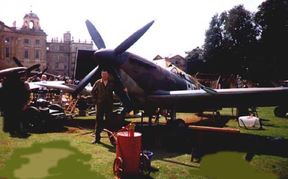
Substantial upgrading of the original Static
steel frame. This was designed by a professional with lots of maths.
Engine bearer in place ready for the Meteor
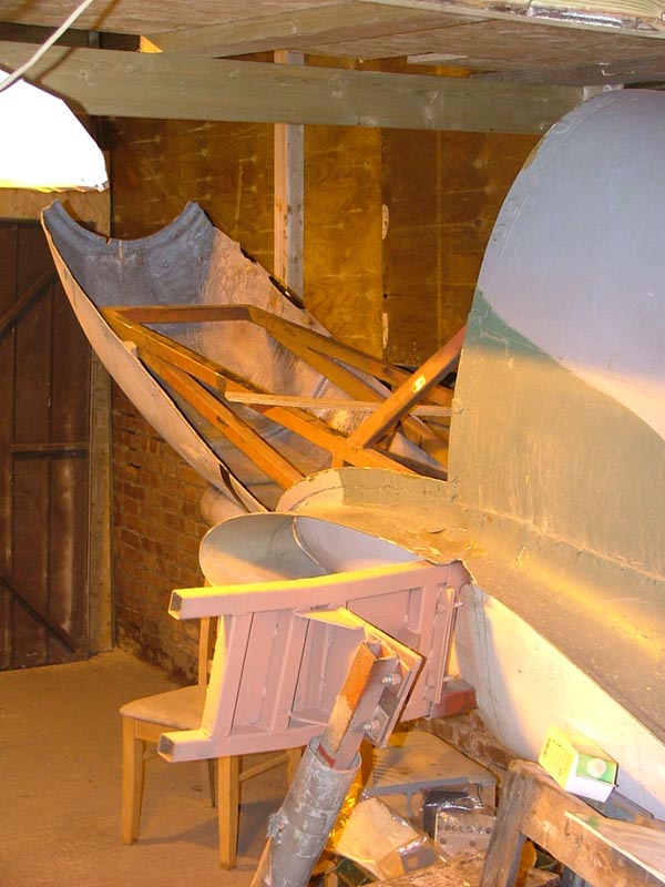
From Tank Engine to Spitfire !!
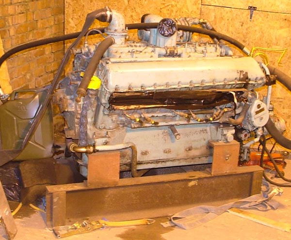
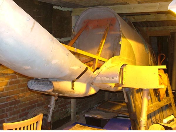
Finally we have
fitted to engine 04/02/07
Progress ought to be a bit more rapid
now, famous last word's.
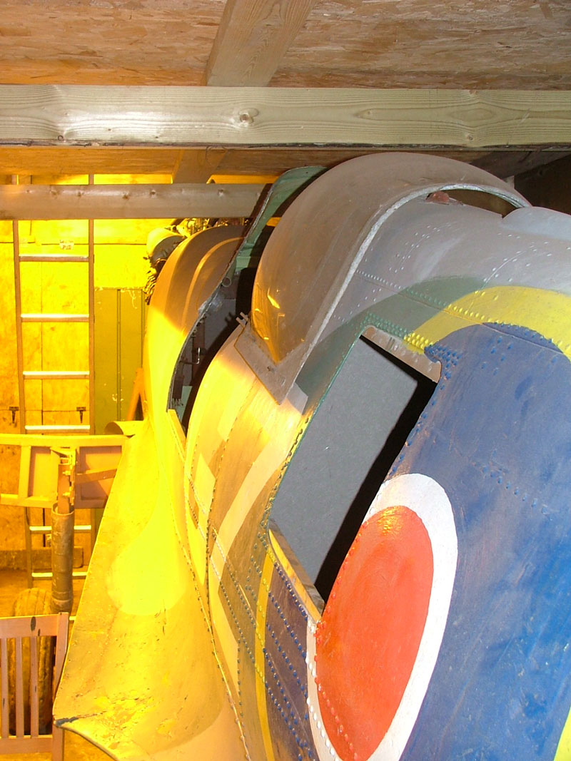
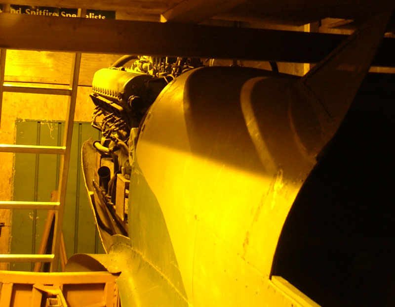
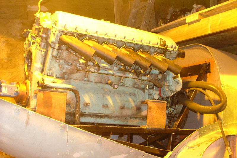
The blue pump mounted to the front of the engine
is the Hydraulic drive for the prop. Meteors do not have reduction gear.


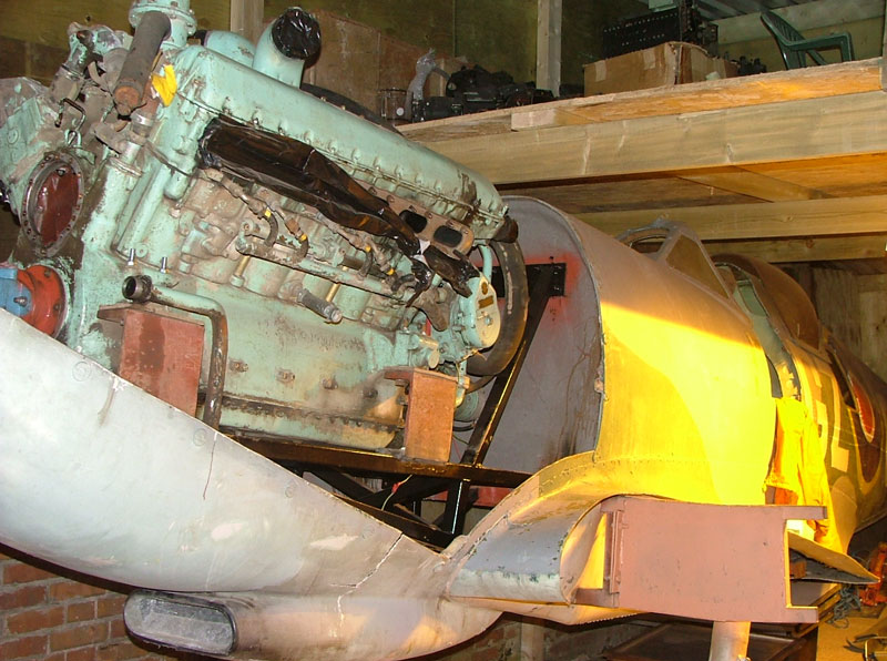
More Picture's added 5th march
2007 Fitting the exhaust stub's.
We have sorted the oil tank you can see it in the
pictures behind the fire wall in front of the instrument panel. We also have a
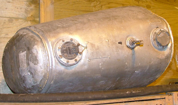
fuel tank, I bought it a couple of years ago with this job in mind and it fits
like a glove. I am mounting it behind the firewall above the oil tank. It has
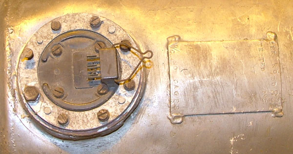
two fuel outlets, perfect, and is also the right depth. The best thing of all it
has a fuel sender and itís a 38 gallon tank, it's Perfect, not a clue what's
it's from but it's dated 1947. I actually have a 38 gallon smithís fuel gauge. I
havenít got the correct 37 gallon, thought 38 was near enough. Looks allot
better now we have got rid of the air intakes and cooling outlet. We are going
to get good quality hose to connect the water, oil system and fuel. The great
thing about the hydraulic prop drive is that you can turn it off. The prop will
operate from the throttle as in the real deal and can be stopped completely.
This way we can run it at shows without all the worries of chopping someone's
head off. Shouldnít cost anymore to insure than a vintage car. Hoping to show
her off at Popham this summer. Lots to do yet
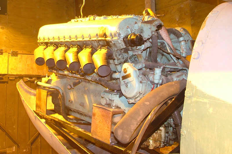
The Fuel tank

Updated 10 MARCH 2007
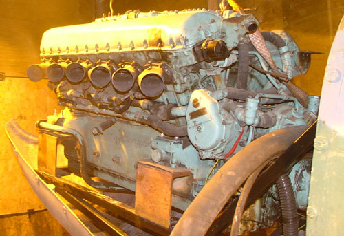
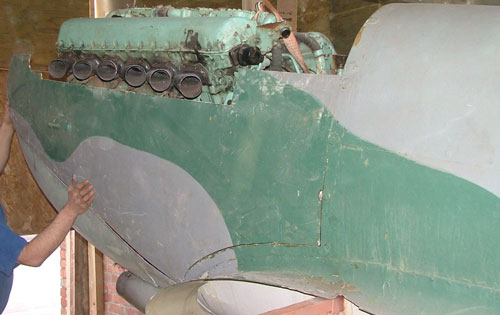
Having discovered the Stubs were
fabricated facing down instead of up they have been put right and the
cowling offered up for fitting.
UPDATED 27/05/07
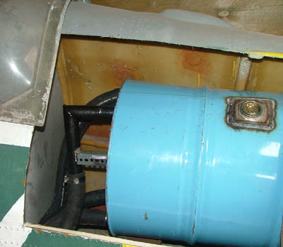
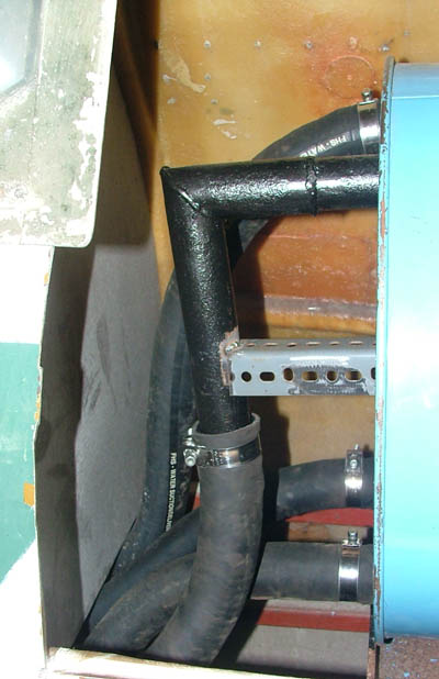
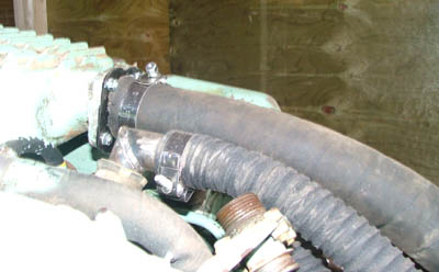
The engine to tank connections have been
completed. The flow of coolant is reversed through the carb manifold and the
rear head outlets and carb manifold flow directly back to the tank.

UPDATED 2106/07
Fuel tank rough first fitting
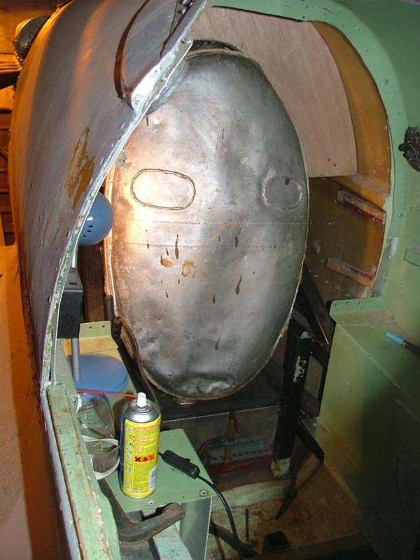
Note the oil tank below the fuel tank. There will
be heat proof matting on the oil tank and several layers of high impact foam.
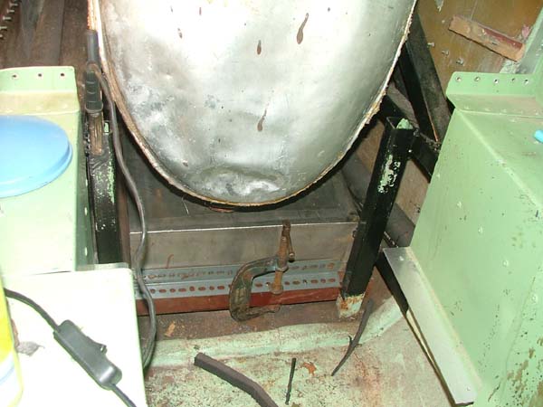
Water tank sealed in. The fuselage will receive a
complete make over when the mechanics are done so don't worry about the rough
fit.

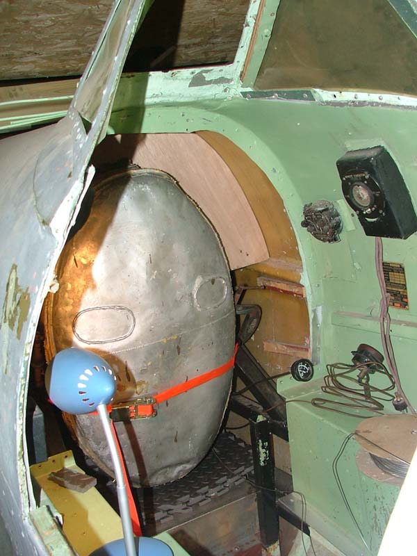
Fuel tank final fit a bar with padding will be
welded in behind the fuel tank to seal it in place.
Note some of the instruments have been threaded
through from the engine ready for panel fitting.
The cockpit will be completely re- done, its a
bit rough at the present. Note the high impact rubber under the fuel tank, there
is a layer of heat proof material over the oil tank although we don't expect any
heat problems with the oil due to the limited running time.

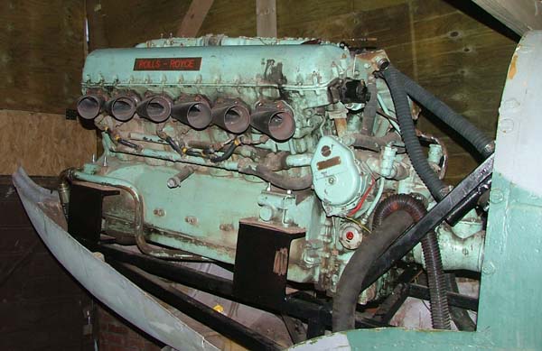
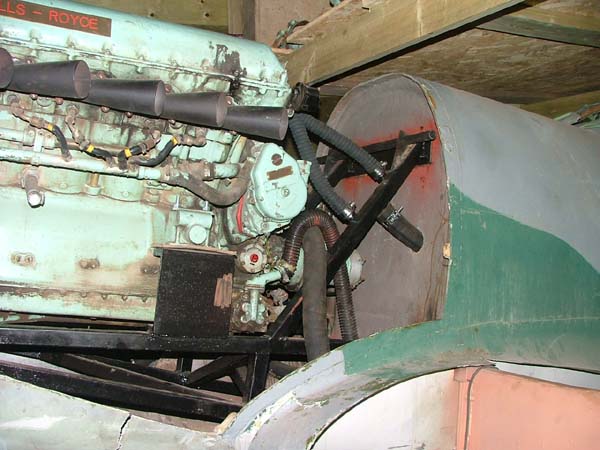
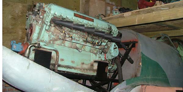
The engine with all oil and water connections in
place. The engine will be cleaned and repainted in black with some original
Merlin rockers
You can see the start of the throttle linkage at
the top of the engine mount. Its the tube on the triangular brackets.
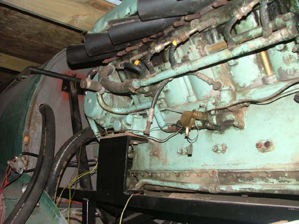
Note the oil pressure gauge sender unit in place
below.
UPDATED 30/06/07
Fuel tank final fix, throttle in place, we had to
use a P47 Thunderbolt throttle as we don not have a genuine spitfire one at this
time. The rudder bars are in place to carry the pedals. Note the top and
underside of the fuel tank is lined with high impact foam. High impact foam to
lesson the vibration to the instrument panel fixed around the bulkhead.

Fuel tank, Oil tank, Throttle and rudder bars all
in place.
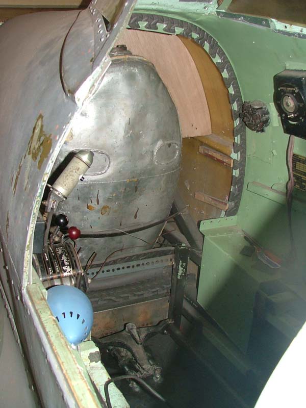
Throttle in place.

Rudder Bars, you can see the fuel lines running
out from the bottom left and right of the fuel tank.

UPDATED 05/07/07
Throttle linkage complete and
working. It may not look pretty but it works.
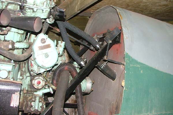
Here is the radiator neck finally fitted to the
carb cooling manifold, this will be connected to a header/overflow pipe
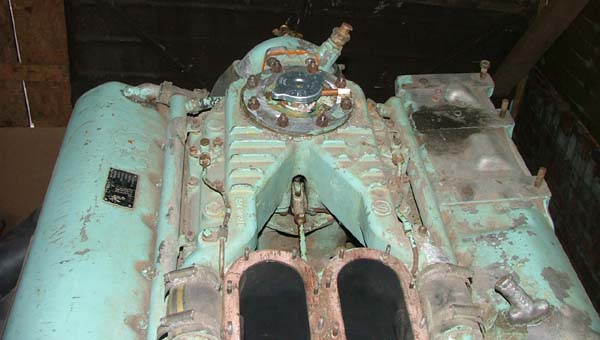
Original stick being fitted


UPDATED 10/07/07
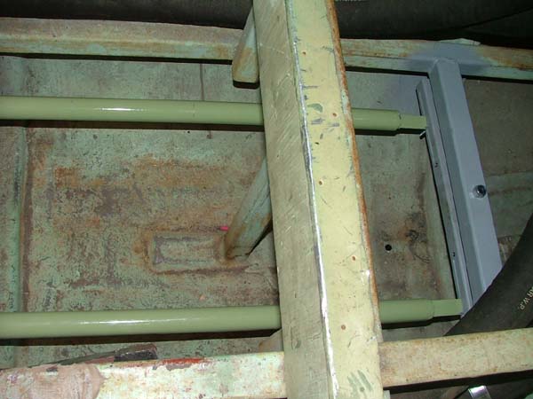
Rudder bar and pedals in place

Rear of the rudder bars. The two holes in the
cross member will have threaded bar attached with solid bar running to the rear
wheel and rudder.
UPDATED 26/07/07
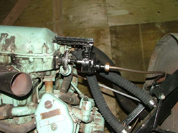
One part of My MKVIII Replica I want to keep as
original as possible is the cockpit. The rev counter was a challenge. The meteor
has an electric generator to drive the rev counter, the original Spit was of
coarse mechanical. The original rev drive ran off the cams at a 4:1 reduction,
i.e. 1/4 engine speed. So I needed a 4:1 reduction gearbox that would fit the
meteor drive for the Rev electrical generator. Tall order!!!! I have a few
generators that work the opposite way they convert mechanical drive from the
Merlin into electrical drive, out of curiosity I took one apart, what a result
they contain a 4:1 reduction gear box. Having removed the armature, I connected
the mechanical drive to the rev counter and gear box and put an electric drill
on the gear box. One problem the meteor rotates in the opposite direction
to the Merlin, that's when luck was really on side for a change, the rev counter
works quite happily regardless of which way the gear box spins. I guess they
designed them that way for different handed engines, I know this kind of rev
counter was used in loads of other RAF types with different engines. Here
is the unit connected up with the flexi drive cable attached.
UPDATED 21/07/07
Tail wheel completed and fitted to rudder bars,
it works!!! The rudder has had lots of
fabrication to fit so that it works. The rudder,
tail plane and elevators will be removable
for transport. Some of the panels have been
prepped for painting.


Instrument panel being wired the fuel gauge now
works with the fuel tank sender
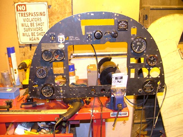
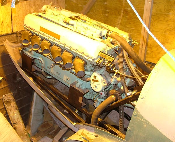
Manual Rev counter drive conversion in place, top
cowling has been test fitted.
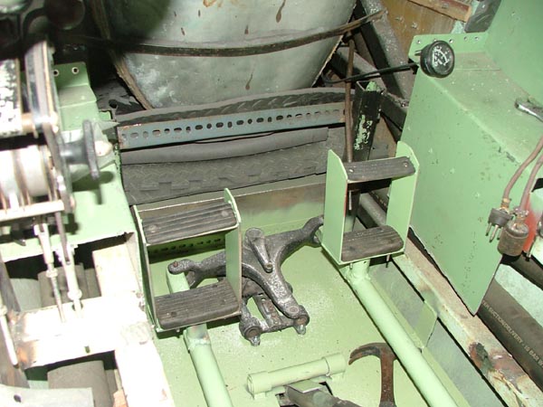
New Rudder pedals fabricated from steel the repro
alloy ones snapped and were like a
honeycombed inside.
1
2
3
4
5
|
